 |
Erriez MCP23017 library for Arduino
1.0.0
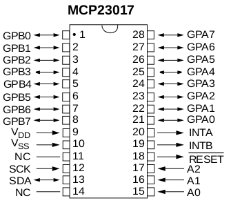
This is a MCP23017 16-pin I2C IO-Expander library for Arduino by Erriez.
|
|
Erriez MCP23017 library for Arduino
1.0.0
This is a MCP23017 16-pin I2C IO-Expander library for Arduino by Erriez.
|
MCP23017 I2C IO expander library for Arduino. More...
#include <Arduino.h>#include <Wire.h>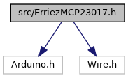
Go to the source code of this file.
Classes | |
| class | ErriezMCP23017 |
| Erriez MCP23017 I2C IO-Expander class. More... | |
Macros | |
| #define | MCP23017_I2C_ADDRESS 0x20 |
| Default MCP23017 I2C address. | |
| #define | MCP23017_REG_IODIR 0x00 |
| Controls the direction of the data I/O for port A. | |
| #define | MCP23017_REG_IPOL 0x02 |
| Configures the polarity on the corresponding GPIO port bits for port A. | |
| #define | MCP23017_REG_GPINTEN 0x04 |
| Controls the interrupt-on-change for each pin of port A. | |
| #define | MCP23017_REG_DEFVAL 0x06 |
| Controls the default comparaison value for interrupt-on-change for port A. | |
| #define | MCP23017_REG_INTCON 0x08 |
| Controls how the associated pin value is compared for the interrupt-on-change for port A. | |
| #define | MCP23017_REG_IOCON 0x0A |
| Configuration register A. | |
| #define | MCP23017_REG_GPPU 0x0C |
| Controls the pull-up resistors for the port A pins. | |
| #define | MCP23017_REG_INTF 0x0E |
| Reflects the interrupt condition on the port A pins. | |
| #define | MCP23017_REG_INTCAP 0x10 |
| Captures the port A value at the time the interrupt occured. | |
| #define | MCP23017_REG_GPIO 0x12 |
| Reflects the value on the port A. | |
| #define | MCP23017_REG_OLAT 0x14 |
| Provides access to the port A output latches. | |
| #define | MCP23017_NUM_REGS 0x16 |
| Total number of registers. | |
| #define | MCP23017_NUM_PINS 16 |
| Total number of pins port A + B. | |
| #define | MCP23017_MASK_ALL_PINS 0xFFFF |
| All 16-pins mask. | |
| #define | MCP23017_MASK_REG_A 0x1E |
| Address mask to select A registers on even addresses. | |
| #define | IOCON_BANK 7 |
| Controls how the registers are addressed. | |
| #define | IOCON_MIRROR 6 |
| INT Pins Mirror bit. | |
| #define | IOCON_SEQOP 5 |
| Sequential Operation mode bit. | |
| #define | IOCON_DISSLW 4 |
| Slew Rate control bit for SDA output. | |
| #define | IOCON_ODR 2 |
| Configures the INT pin as an open-drain output. | |
| #define | IOCON_INTPOL 1 |
| This bit sets the polarity of the INT output pin. | |
| #define | REG_IOCON_VALUE |
| Default MCP23017 configuration. More... | |
MCP23017 I2C IO expander library for Arduino.
Source: https://github.com/Erriez/ErriezMCP23017 Documentation: https://erriez.github.io/ErriezMCP23017
1 This library is designed for MCP23017 with I2C interface.
2 This library does not support the MCP23S017 with SPI interface. Workaround: None, use another library, or add SPI support to this library.
3 The INTB is not enabled in this library, because. INTA and INTB interrupts are ORed to INTA with configuration bit MIRROR=1 in IOCON register. Workaround: The application shall only use INTA.
4 Port, direction and pull-up states are cached in variables for speed: No additional register reads are needed.
1 The MCP23017 does not support rising or falling edge interrupts. Workaround: None: The MCP23017 support only the following interrupts:
2 Note: The register IODIR bits are reversed: 0: Output 1: Input Workaround: Be careful with interpreting register IODIR.
1 The INTA pin is released when reading from register GPIO or INTCAP. This happens when the application calls function pinRead() or portRead(). This is a documented chip limitation. Workaround: None.
2 Register INTF captures only one pin change. The MCP23017 does not update register INTF when multiple interrupts occurs at the same time. Workaround:
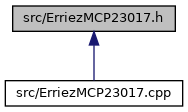
Definition in file ErriezMCP23017.h.
| #define REG_IOCON_VALUE |
Default MCP23017 configuration.
Definition at line 124 of file ErriezMCP23017.h.
 1.8.13